

Utilization of RepetitiveSurge Oscillograph (RSO) in the Detection of Rotor Shorted-Turns in LargeTurbine-Driven Generators
Isidor Kerszenbaum Clyde Maughan
Southern California Edison Maughan Generator. Consultants
San Clemente, CA Schenectady, NY
Abstract – The use of theRSO technique for the detection of shorted-turns in the field winding of largesynchronous generators with cylindrical rotors has become more widely acceptedin North America in the last few years. The test procedures have beenpreviously described in a number of publications. However, interpretation ofthe RSO traces haven not been well defined, and the benefits and limitations ofits application are not well understood. Using some recent experience, thispaper is intended to provide guidance on signal interpretation and to clarifythe main advantages and limitations of the application of the RSO testing.
I. INTRODUCTION
Assessing the condition ofhigh-speed (cylindrical-rotor) turbine-generators has always been a challenge.This is especially true of the field windings, which are largely inaccessibleunder the wedges and retaining-rings. Limited access for inspection may beavailable on some rotor windings through radial ventilation holes in the wedgesand under the retaining-rings.
The opportunityfor tests is equally limited. The copper resistance can be accurately measured,but if a fracture is developing, the test will not reveal the condition, solong as there is good electrical connection at the crack. Groundwall insulationover-voltage test is generally not recommended and the low-voltage insulationresistance (“megger”) test mainly relates only to cleanliness and moisture.
Turn insulation shorts are animportant and relatively common field winding failure mechanism. In operation,turn shorts may be revealed by low and/or erratic field temperature readings.(But the instrumentation behavior may also just be the result of a defectivemeter or electrical circuit). The most reliable way of detecting shorted turnsin operation is with the use of a rotor flux monitor. The probe is asimple, relatively inexpensive device; it will quite accurately tell the numberof shorted turns and indicate the coils in which the shorts are located. Butinstalling the probe generally must be done with the field removed and probeshave not yet been installed in many generators.
At stand-still, if a significantnumber of shorts exists, copper resistance will be lower than on the originalwinding – in proportion to the percentage of shorted turns. But this test givesno information as to location of shorts. Where physical access is available tothe copper of the turns or coils, probing for voltage drop or resistance candetermine the exact coil (or turn) that is shorted. But
performingthis test is time-consuming and generally some field disassembly is needed,e.g., retaining ring removal.
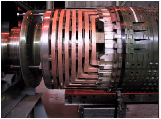
Fig. 1 Typical fieldendwinding
The RepetitiveSurge Oscillograph (RSO) test overcomes many of the above limitations forshorted-turns testing, both at stand-still and with the rotor at speed. The RSOtest is the subject of the remainder of this paper.
II. BASIC DESCRIPTION OF THEOPERATION OF THE RSO
Figure 1 above shows theend-section (“overhang” or “endwinding”) of a typical cylindrical rotor(“field”) winding.
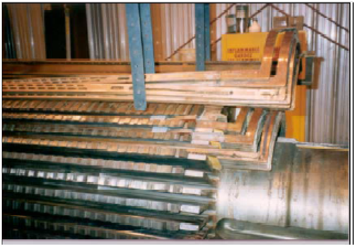
Figure2 shows the middle-section of a field winding.
Fig. 2 Typical field winding showing both the middle andend sections. Some of the turns are shown lifted from the slots.
Both figuresabove clearly show that a distinguishing feature of cylindrical rotorfield-windings is their symmetry. This characteristic is common to all largesynchronous cylindrical rotors, belonging to either 2-pole or 4-pole machines.Under operating conditions, the field winding carries a DC current. Thus, theproper circuit representation is simply a resistor. However, if alternatingcurrents flow thru the winding, a complete circuit representation will alsoinclude inductances and capacitances.
Inspectionof both figures 1 & 2, show that part of the winding (the “middle”section), is in close proximity to the rotor forging. Figure 3 depicts thecross section of a typical slot showing the conducting bars and their proximityto each other and to the forging.
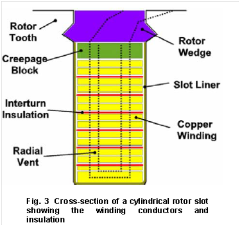
Theproximity between turns exists both in the middle and end sections of thewinding, while the proximity to the forging exists only in the middle-section,inside the slot. This geometry results in a winding with resistance,capacitance and inductance that is very specific to each design, but that hassome common characteristics to all. Calculation of the circuit components isnot simple, but their measurement is. For a low-frequency representation, a lumpedcircuit representation is easily obtained. For high frequencies, a distributedcircuit representation is required.
The RSO is an instrument that injects two identical(“twin”) signals – one from each end of the winding. In addition, a built-in,or separate oscilloscope is used to capture the signals at the other side ofthe winding, and any reflections that occur. Figure 4 shows the typical RSOarrangement, including power source, connections and oscilloscope.
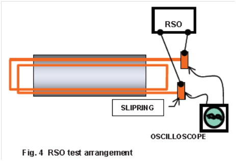
The twinsignals generated by the RSO and shown schematically in Figure 5, have a fastrise time equivalent to a high frequency waveform. The impedance presented bythe rotor field to this high frequency signal is the wave impedance ofthe R-L-C distributed circuit. From Time Domain Reflectometry theory it isknown that a signal encountering an abrupt change in wave impedance will resultin a reduced thru signal and a reflected signal. Given the strongsymmetry of the field winding, all thru and reflected signals, in the absenceof a shorted turn or a ground, will be almost identical. However, if adiscontinuity of the wave impedance, created by a shorted turn or a groundexists, both twin signals will generate different thru and reflected waveforms.The RSO takes advantage of this fact to detect shorted turns and grounds.Because grounds of the field winding can be detected by other means, the RSOmain purpose is the detection of shorted turns.
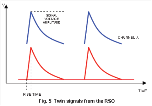
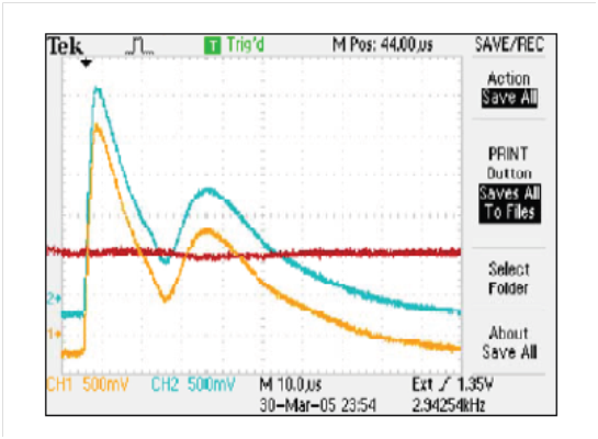
Fig. 6 – RSO twin signals as pickedfrom a rotor winding without shorted turns.
The quasi-straight line is the sum ofthe signals with one of them inverted
The frequency of the twin signals and rise time arespecific to eachRSO vendor, thou they are typically in the kHz region with rise times ofseveral microseconds. Figure 6 shows the typical twin signals as picked up froma rotor without winding shorted-turns or grounds.
As shown on Figure 6, it makes iteasier to identify the existence of shorted-turns or other anomalies, byinverting one of the signals and summing it up with the other. This can be donein the oscilloscope. The resulting waveform is a straight line, if shorts arenot present, or a line with kinks on it, if there are shorted-turns. Figure 7shows typical traces from a rotor with shorted-turns present.
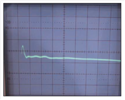
Fig. 7The waveform shows the summed up signal from a rotor with a shorted-turn.
III.RSO APLICATION ISSUES
As explained in the Introductionabove, there are a number of techniques for detecting shorted turns inturbo-generator rotors. The RSO has a prominent place among them. The RSO,first used in the Great Britain in the 1970’s, has gradually penetrated NorthAmerica from the middle 1990’s. The RSO’s great advantages are: its simplicityuse and swift setup and measurement times, as well as the fact all readings canbe taken from the collector rings (and the case of brushless units, from theend of the field winding next to the diode-wheel). The main use of the RSO ison rotors standing still, either assembled in the stator or outside. But,asshown below, the RSO can be used on rotating fields with collector rings. Thishas been done with great success by the authors of this paper and others. Thiscapability is particularly important for those cases where a rotor fluxmonitor is not permanently installed in the airgap.
The RSO cannot pinpoint the exactlocation of a shorted-turn, although experienced users can develop thedexterity that allows them to identify with high likelihood the coil and polewhere a short(s) may be located. Figure 8 shows multiple shorted turns on thefirst (“small”) coils of a rotor. A kink on the resultant curve close to thebeginning of the trace indicates a shorted-turn close to one of the sliprings.As the kinks move away from the beginning of the curve, they indicateshorted-turns in the
larger coils.(The “small” coil is the coil closest to the pole-face of the rotor, while the“largest” coil is closest to the quadrature axis of the rotor).
It is well known that a largeportion of all shorted-turns tend to “disappear” when the rotor is atstand-still. The reason is that those shorts depend on the centrifugal forcesencountered while the rotor is turning a high speed.
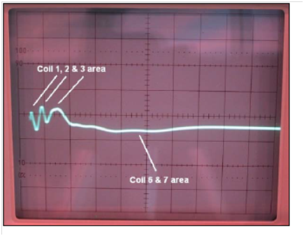
Fig. 8 RSO traceshowing multiple shorted-turns
Some of these pressure-dependentshort may be detected with the rotor at standing-still, taking measurements atvarious rotor angles, i.e.: the rotor is rotated by hand and stopped at variousangles until it moved a full turn. Often the RSO will detect a short in onerotor angle, and not in others. For those shorts that will completely go awaywith the rotor standing still, the “spinning RSO test” (describe in Section IV,below) can be carried out.
One concern of is how safe is theRSO to personnel and the field winding insulation. Is there an operator hazardand can the test create shorted-turns or grounds where they didn’t previouslyexist? All RSO instruments generate twin signals in approximately a 5 to 15volt range, thus presenting essentially no personnel hazard. A typical large4-pole field, with, say 600 VDC and 400 turns, results in 1.5 volts/turn, andat forcing field condition of 2.5 times rated voltage, it will equal about 3.75volts/turn. Although the voltage distribution of the RSO signals is not linear,the 5 to 15 volts applied by the RSO to the entire winding are certainly of thesame order of magnitude or lower. Also, the source impedance of the RSO instrumentis very high resulting in mere milliamps at the most, of current flowing fromthe RSO, even under a full short circuit. Finally, the low voltage output fromthe RSO allows testing personnel and maintenance personnel to work on the rotorwinding with the RSO connected and operational. This feature is very helpfulduring some stages of a winding repair or installation, when any mistakeresulting in a shorted-turn can immediately be detected and corrected.
One must be careful before calling any kink on thecurve a shorted-turn. A winding with extremely distorted turn in the endwindingmay exhibit enough impedance asymmetry to result in a somewhat distorted RSOtrace. A ground fault will show up as a very large kink, thus making iteasy to differentiate from a shorted-turn. Thus, experience is important inthe application of this technology.
IV. SPINNING RSO
Figure 9 shows the RSO measuring setup for testing rotors atspeed. It is critical when carrying out an RSO test with the rotor spinning,that all connections to the exciter are open. One proven method is by removingall commutating brushes and installing for the duration of the test one or twobrushes per slipring. These brushes must be insulated to the brush-holder. Toinsulate the brushes, they may be slightly grinded and coated on their sidewith a thick layer of insulating epoxy paint. Then, the pigtail of the brush isconnected to the RSO output and the oscilloscope. The RSO instrument groundmust be connected to the spinning shaft either by holding (carefully!) againstthe shaft a grounded braid on a stick, or by connecting to the shaft groundingbrushes. An alternative method to connecting the RSO to the winding is byconnecting it to the plus and minus polarities of the brushgear, but openingthe circuit from the exciter side ( Figure 9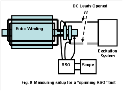
Fig. 9 Measuring setup for a “spinning RSO” test
V. CONCLUSIONS
The RSO is an excellent tool in the bag of tools existing todiscover shorted turns. However, like any other tool, it must be used only whenapplicable, and with the insight of experience. The goal of this paper is tomake potential users aware of the capabilities of the RSO, as well as to alertthem to its limits.
VI. REFERENCES
EPRI TR-114016: “On-line Detection ofShorts in Generator Field Windings. RSO ScopeExcitation System DC Leads Opened Ro